
Introduction
NRF24L01 is a wireless transceiver module which operates in the 2.4GHz ISM frequency band. It is the range of operation of the module. It is used to communicate data wirelessly which is specially designed for ultra-low power applications.It can transmit data at a rate
up to 2 Mbps. The data rate can be altered by us i.e 256kbps and 1mbps and 2mbps.This module can use 125 different channels which makes possible to have network of 125 independently working modems in one place. We can use 4 power range for increasing the range the max is of 1.1km we different power level are Min ,Low ,High ,Max.
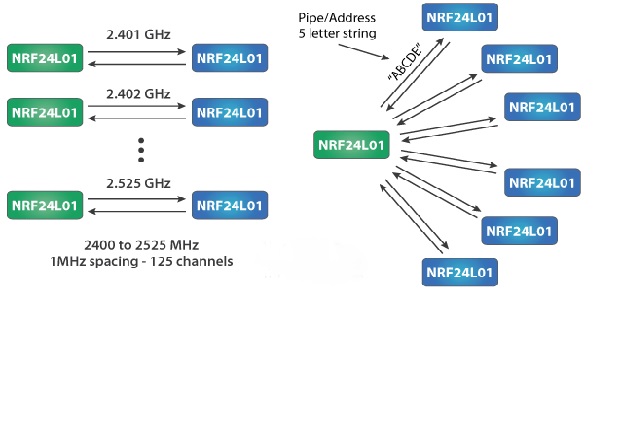
Each channel has up to 6 addresses that means it can communicate with 6 other devices simultaneously. As we can see in the diagram one NRF module communicating with six channel at a time also we can see the channel spacing of the NRF module.
The communication range is up to 1100 meters and it specially designed for ultra-low power applications. It operates on 1.9V to 3.6V power supply range, it takes 12mA of current during transmission mode which is even less than a single LED.
NRF module pins and its function
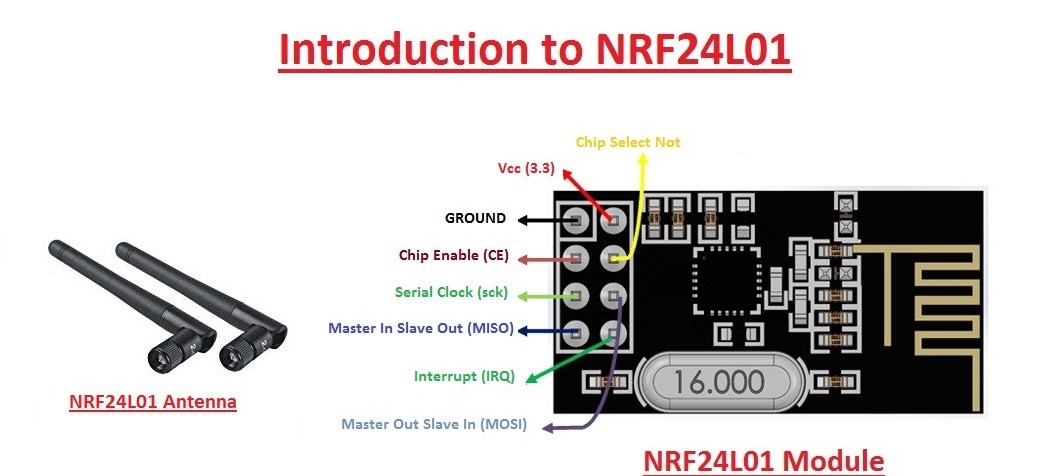
The module consists of 8 pins out of which we use only seven as our usage is concern about only the 7 pins. This module works on 3.3volts Arduino has 3.3volts pin. Uniko ekam board doesn’t have that pin but don’t it can work with 5volts pin in this board as when we connect the board to pc or laptop it doesn’t generate the output of 5v but lower then that that help our module through working. From this module pin CE and CSN are most important we need to declare these to pin in program . all the other pins need not to be declared in the program. The antenna provided with the module is useful for the increasing the range of communication i.e upto 1.1km
Interfacing with Arduino
Components: Two Arduino board , Two NRF24L01 module with antenna ,connecting wires.
Library used: SPI.h ,nRF24L01.h ,RF24.h
This three library is used for using the NRF module this can be added by going into librabry manager in sketch menu of the Arduino ide and download library RF24 by TMRH20
Connection:
- ATTACH THE ANTENNA TO THE MODULE
- CSN – DIGITAL PIN 8
- CE – DIGITAL PIN 7
- MOSI – DIGITAL PIN 11
- MISO – DIGITAL pin 12
- SCK – DIGITAL PIN 13
- V+ – VCC OF THE BOARD
- GND – GROUND OF THE BOARD
working
- First do the connection as discussed earlier then while writing the code we need to configure one module as transmitter and other as receiver if we perform the unidirectional operation for transmitter we write in code object.stopListening() in the setup fuction and for receiver we write object.startListening() here object is the name we provide to the variable for using the NRF module and in that object we provide pin no of CE and CSN as arguments
- When all the connections are made and program for both the NRF module is written we are set to operate it
- We provide the address of the other NRF module which we will use for communication as there are 125 channel we can use any one from that for communication the address of communication at both the end should be same
- The which we need to send is stored in the array at the receiving we create the empty array which will store the data it has received and print using the Serial.print()
- Thus we can open the serial monitor of the reviver’s code to see the data that is received
- The other property which this module possess is the bidirectional communication
- This can be done by using both the function i.e the stopListening and startListening for both the module thus both the module can send data as well as check if the any data is received or not and display it
- One thing we need to keep in mind is that the module sends the data in the form in byte only so we create a byte array that convert our data into bytes
code’s for transmitter and receiver
Transmitter
Receiver
How to use the code
- First copy the code and paste in the Arduino Ide
- secondly copy the receiver code and paste in another window of ide
- upload the transmitter code in one board and receiver code in another board
- remember select the different port for both the board for uploading
Things to remember
- For unidirectional communication we use only one pipe(address for communication)
- And this address which we use for reading and writing should be same on both the end
- For bidirectional communication we use 2 address(pipe) and it to has to be same on both end otherwise the communication is not achieved.
- We can use the led or buzzer at the receiver end or sender end for indicating the reception
